





What Is a Reversing Contactor? Working Principle, Components & Applications?
Summary
Reversing a motor isn't simply about changing its direction. The switching sequence must be controlled carefully to protect both the motor and the electrical system. This guide explains what is reversing contactor, its major components, operating sequence, and why it plays such an important role in industrial motor control applications requiring reliable forward and reverse operation.
Key Takeaways
- A reversing contactor enables a three-phase motor to rotate in both forward and reverse directions by changing the phase sequence supplied to the motor.
- The system uses two power contactors along with mechanical and electrical interlocks to prevent both contactors from operating simultaneously, ensuring safe motor reversal.
- Reversing operation works by interchanging any two supply phases, which reverses the rotating magnetic field and changes the motor's direction of rotation.
- An overload relay protects the motor from excessive current during operation, while the control circuit, push buttons, and auxiliary contacts provide safe and reliable switching.
- Reversing contactors are widely used in conveyors, cranes, hoists, machine tools, industrial doors, and other applications that require controlled bidirectional motor movement.
- Selecting the right reversing contactor requires considering motor ratings, utilisation category, coil voltage, switching frequency, and proper protection coordination to ensure reliable long-term performance.
Table of Contents
Introduction
Electric motors rarely spend their entire life turning in one direction. Think about a crane lifting and lowering loads, a conveyor that occasionally needs to reverse, or an industrial hoist moving materials back and forth. None of these applications can rely on manually swapping wires every time the motor changes direction. There has to be a safer and much faster method.
That is exactly where a reversing contactor becomes valuable. Although it looks similar to a standard contactor, its purpose is quite different. Instead of merely switching power on and off, it changes the motor's direction by altering the phase sequence supplied to the motor. Understanding how does a reversing contactor work makes motor control systems much easier to understand and troubleshoot.
What is a Reversing Contactor
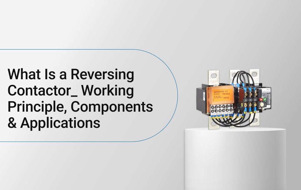
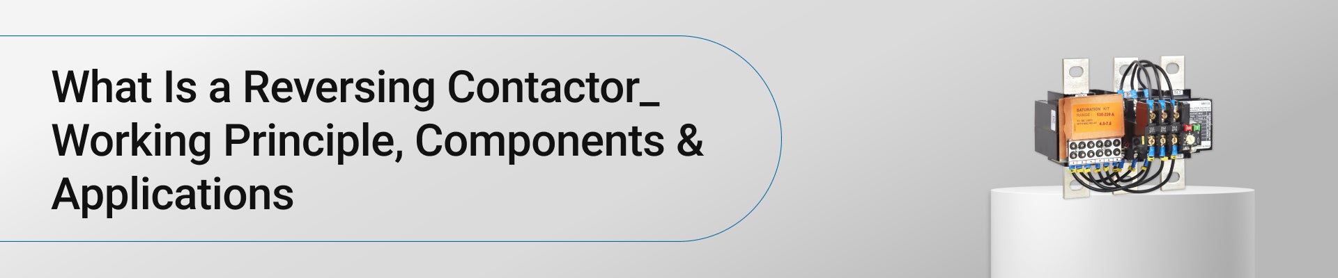
Many people assume it is a special type of motor starter, but that isn't quite accurate. A reversing contactor is actually an arrangement of two contactors designed to operate together so a three-phase motor can rotate in either forward or reverse direction. One contactor connects the motor for normal phase rotation, while the other swaps two phases to reverse the motor.
When someone asks what is reversing contactor, the simplest answer is that it is a motor control device that safely changes rotational direction without physically rewiring the motor. Mechanical and electrical interlocks ensure both contactors cannot close at the same time.
Key Components of a Reversing Contactor
A reversing assembly is more than two contactors placed side by side. Every component has a specific purpose, and together they ensure dependable operation. Even a small missing element, such as an interlock, can create serious electrical faults during motor reversal.
Two Power Contactors
The heart of the assembly consists of two contactors. One controls forward rotation, while the other controls reverse rotation by exchanging two incoming phases. A properly selected power contactor must match the motor voltage, current rating, utilisation category, and switching duty. Although both contactors appear identical, their wiring differs so each establishes a different phase sequence when energised.
Mechanical Interlock
Imagine both contactors closing together. Instead of reversing the motor, they would effectively short different phases together, creating a dangerous fault condition. A mechanical interlock physically prevents simultaneous operation. If one contactor is already closed, the second simply cannot move into the closed position until the first has completely released.
Electrical Interlock
Mechanical protection alone isn't considered sufficient for reliable motor control. Auxiliary normally closed contacts are wired into each contactor coil circuit, creating an electrical interlock. Whenever the forward contactor energises, the reverse contactor coil circuit automatically opens. The opposite happens during reverse operation. This simple arrangement adds another layer of protection and greatly improves operational reliability.
Overload Relay
Changing direction does not eliminate the possibility of overload. Motors can still draw excessive current because of mechanical jamming, bearing failure or an overloaded driven machine. An overload relay continuously monitors motor current and disconnects the control circuit whenever the preset value is exceeded. It protects the motor windings from overheating rather than clearing short-circuit faults.
Control Circuit and Push Buttons
The operator interacts with the system through the control circuit instead of the power circuit. Typically, separate Forward, Reverse and Stop push buttons are provided along with auxiliary contacts for holding circuits. Control transformers, indicator lamps and emergency stop devices may also be incorporated depending on the application. The arrangement remains simple but highly dependable.
How Does a Reversing Contactor Work?
Understanding the sequence is often easier than memorising wiring diagrams. Once the relationship between phase rotation and motor direction becomes clear, the operating principle makes perfect sense. Every switching step is carefully controlled to avoid electrical faults while allowing smooth changes in motor rotation.
Forward Operation
Pressing the Forward push button energises the forward contactor coil. Its main contacts close and supply the three phases to the motor in their normal sequence. Auxiliary contacts establish a holding circuit so the contactor remains energised after the push button is released. During this time, the electrical interlock prevents the reverse contactor from operating.
Reverse Operation
When reverse operation is requested, the forward contactor must first de-energise completely. Only then can the reverse contactor energise. Two incoming phases are exchanged before reaching the motor terminals, causing the rotating magnetic field to reverse. Since the magnetic field changes direction, the motor shaft also rotates in the opposite direction. This sequence illustrates the reversing contactor working principle.
Phase Sequence Reversal
A three-phase induction motor changes its direction whenever any two supply phases are interchanged. That simple electrical principle forms the basis of the entire reversing arrangement. If the normal sequence is L1-L2-L3, reversing two phases changes the rotating magnetic field. The motor immediately develops torque in the opposite direction without requiring internal motor modifications.
Importance of Interlocking
If both contactors closed together, different supply phases could become directly connected through the contactor assembly. The resulting fault current would be extremely high and could damage contactors, cables and upstream protection devices. Interlocking prevents this possibility, making it one of the most important safety features in any motor reversing circuit.
Understanding the Wiring Arrangement
A reversing contactor diagram helps visualise how the forward and reverse power circuits are connected. Instead of studying the motor alone, the diagram shows the relationship between incoming phases, outgoing motor terminals, auxiliary contacts and interlocking arrangements. For technicians, reading the wiring correctly often makes installation and troubleshooting much faster.
Applications of a Reversing Contactor
Once the operating sequence is understood, the next question is where this arrangement is actually used. In reality, any machine that needs controlled bidirectional movement can benefit from it. The key is not simply reversing the motor, but doing so safely, repeatedly, and without placing unnecessary stress on the electrical control system.
Conveyors and Material Handling
Production lines often need to move products in both directions. If a package becomes misaligned or the line requires clearing, the motor must reverse quickly. A forward and reverse contactor arrangement makes this possible without manual rewiring. Operators can change the direction using the control circuit, helping reduce downtime while maintaining consistent movement throughout the conveying process.
Hoists, Cranes, and Lifting Equipment
Cranes and hoists constantly alternate between lifting and lowering loads. Reliable directional control is essential because sudden or incorrect switching can interrupt operations and increase equipment wear. A properly designed reversing control circuit ensures the motor changes direction only after the previous operation has ended, giving smooth and controlled movement during routine handling of materials.
Machine Tools
Industrial machines such as lathes, drilling machines, and milling equipment frequently require reverse rotation for specific machining operations. For example, tapping threads often demands forward rotation followed by controlled reverse movement. Using a dedicated reversing control arrangement simplifies this process and allows operators to switch directions accurately without making changes to the motor connections.
Sliding Gates and Industrial Doors
Automatic gates, rolling shutters, and industrial doors need motors that can open and close on command. Direction changes occur many times each day, making dependable switching particularly important. Combined with limit switches and suitable control logic, a reversing arrangement provides repeatable operation while reducing unnecessary stress on the motor and associated mechanical components.
Pumps and Special Industrial Equipment
Although most pumps rotate in one direction, certain industrial processes require periodic reverse operation for cleaning, flushing, or clearing blockages. Similar requirements are found in mixers, winding machines, and specialised process equipment. In these applications, the motor control system must coordinate directional changes carefully to protect both the driven equipment and the electrical installation.
Also Read: What is a Magnetic Contactor? Principle, Types & Advantages
Conclusion
A motor control system is only as dependable as the components that control it. Reversing motor direction may appear straightforward, but it requires proper phase sequencing, dependable interlocking, and correctly selected switching devices to ensure reliable operation over thousands of switching cycles.
Whether the application involves conveyors, hoists, machine tools, or automated doors, choosing quality control components helps improve performance and minimise unexpected downtime. For professionally engineered motor control products and dependable electrical solutions, explore the range available through Lauritz Knudsen SmartShop, where solutions are designed to meet the demands of modern industrial and commercial installations.
FAQs
Q. Can a reversing contactor be used with both squirrel cage and slip ring induction motors?
Ans. Yes. It can be incorporated with both motor types, provided the overall control circuit and starter arrangement are designed to suit the motor's operating characteristics and application requirements.
Q. Is a timer required in every reversing motor control circuit?
Ans. Not always. However, timers are often added where a short delay between forward and reverse operation is needed to minimise mechanical stress and reduce electrical switching transients.
Q. How do auxiliary contacts help in a reversing circuit?
Ans. Auxiliary contacts are used for functions such as electrical interlocking, seal-in (holding) circuits, signalling, and integrating the motor starter with other control devices or automation systems.
Q. What should be checked before selecting contactors for a reversing application?
Ans. Important considerations include motor full-load current, supply voltage, utilisation category, coil voltage, short-circuit protection coordination, operating frequency, and the expected number of switching operations.
Q. Can a reversing motor control circuit be integrated with a PLC?
Ans. Yes. In many modern installations, programmable logic controllers (PLCs) issue the forward and reverse commands while the contactors perform the actual power switching, combining automation with reliable motor control.
Comments