





What is a Single Phase Energy Meter and How Does It Work?
Summary
A single phase energy meter records the electricity used in a home or shop. This guide explains the single phase energy meter working principle in simple steps. It covers the main parts and the correct single phase energy meter connection. Readers also learn where the meter is used and how it differs from a three phase type. Electricians, buyers and homeowners can use these facts to read bills, check wiring and choose the right meter for each load.
Key Takeaways
- The meter measures energy in kilowatt hours (kWh). One kWh equals 1,000 watts used for one hour.
- Single phase energy meter components include a current sensor, a voltage sensor, a metering chip, a display and a pulse LED.
- Induction meters use a rotating aluminium disc. Static meters use a metering IC and have no moving parts.
- Four terminals are standard. Terminal 1 is phase in, 2 is phase out, 3 is neutral in and 4 is neutral out.
- Single phase energy meter applications include homes, shops, sub metering, solar export and EV charging.
- Typical ratings are 230 V, 50 Hz and accuracy class 1.0.
Table of Contents
• What is a Single Phase Energy Meter?
• Single Phase Energy Meter Components
• Single Phase Energy Meter Working Principle
• Single Phase Energy Meter Connection
Introduction
Every electricity bill starts with one small box. It hangs on a wall near the service cable. Most people look at it only when the bill seems too high. Yet the box does careful work. It counts every unit of energy that a home or shop draws. That count then sets the bill. In reality, a faulty or badly wired meter can cost money and cause disputes. So the basics matter. This guide explains what the household meter is, how its parts work and how it is wired. It also covers where it is used.
What is a Single Phase Energy Meter?
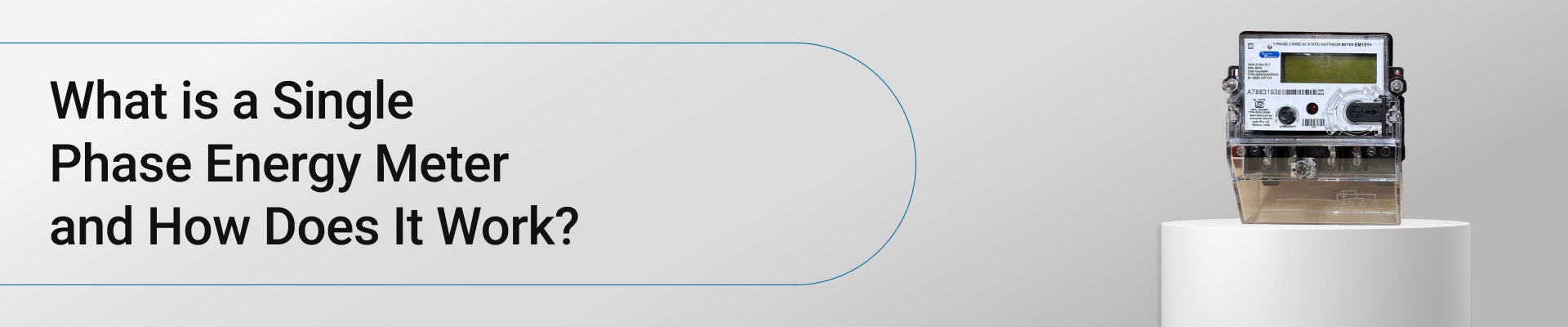
This device measures electrical energy in kilowatt hours (kWh). It works on a two wire supply of 230 V and 50 Hz. Most homes, shops and small offices use this supply. A three phase energy meter serves larger loads on a four wire supply. The meter reads both current and voltage. It then multiplies them over time. The single phase energy meter working principle rests on this link between power and time. Accuracy class 1.0 is common, so error stays within one percent. Indian static meters follow IS 13779.
Single Phase Energy Meter Components
The single phase energy meter components differ by meter type. Older meters use a rotating disc. Modern meters use a chip. Both types need a way to sense current and voltage. Both need a display. Both need a way to store the reading. Think about this. A meter must run for 15 years with no service. So each part must be stable and precise. The sections below cover four main groups. They explain the sensing parts, the metering chip, the display and the power supply. Together they form a small measuring system.
Current and Voltage Sensing Elements
The meter needs two signals. One shows current. The other shows voltage. In electromechanical meters, a current coil of thick wire sits in series with the load. A voltage coil of fine wire sits across the supply. In static meters, a shunt resistor or a small current transformer senses current. A resistor divider scales voltage down to a few millivolts. Both signals then feed the metering chip.
Rotating Disc and Braking Magnet
In induction meters, an aluminium disc turns between the coils. A permanent magnet acts as a brake. The brake makes disc speed match the power used. Without it, the disc would speed up without limit. Jewel bearings reduce friction. Adjusting screws and a lag plate correct small errors. These parts need clean, dry air to hold accuracy over many years.
Metering IC, Microcontroller and Display
A metering IC converts analogue signals to digital data. It samples them thousands of times each second. It then multiplies voltage and current to find power. A microcontroller adds up the energy and stores it in memory. An LCD shows kWh, voltage, current and other data. A pulse LED blinks in step with energy use. Common values are 1,200 or 1,600 pulses per kWh.
Power Supply, Register and Terminal Block
A small power supply feeds the electronics from the mains. A capacitor or a transformer drops the voltage. In electromechanical types, a gear train drives a register with numbered drums. The terminal block holds four terminals. A sealed cover protects them. Seals also show any attempt to tamper. The case is usually flame retardant polycarbonate.
Single Phase Energy Meter Working Principle
Two designs rule the market. The induction meter uses magnetism and a spinning disc. The static meter uses electronics and no moving parts. The goal is the same. Both multiply power by time to get energy. Think about this. Energy is power used over a period. A 1 kW heater running for two hours uses 2 kWh. The meter does this sum all day without a pause. Smart meters add two way data links on top. The sections below explain the induction type, the static type and the way energy is recorded.
Induction Disc Operation
Two electromagnets sit on either side of the disc. One carries load current. The other carries a current set by supply voltage. The two fluxes are shifted by about 90 degrees. They induce eddy currents in the disc. These currents interact with the fluxes and create torque. Torque is proportional to power. The braking magnet balances this torque. So disc speed matches power, and total turns match energy.
Static Meter Operation
Here, the meter takes samples of voltage and current. An analogue to digital converter, often 16 or 24 bit, turns them into numbers. The metering IC multiplies each pair of samples. It adds the products to find active power. The microcontroller then adds power over time. This gives energy. No part moves, so wear is low. Accuracy stays steady over wide temperature and load swings.
Energy Registration and Pulse Output
The result shows on a register. A mechanical register uses gears. One disc turn equals a set fraction of a unit. A static meter keeps the count in non volatile memory. It holds the value even after a power cut. The pulse LED allows quick accuracy tests. A test bench counts pulses and compares them with a reference meter. Billing uses the difference between two readings.
Single Phase Energy Meter Connection
Correct wiring protects the meter and the user. A single phase energy meter wiring diagram shows four terminals in a fixed order. Supply enters on the left. The load leaves on the right. Safety comes first. Only a licensed electrician or the utility should install a meter. The supply must be off. A tester must prove that the lines are dead. For example, a loose neutral can cause voltage swings and wrong readings. Local utility rules also apply. The sections below show the diagram, the steps and the final checks.
Single Phase Energy Meter Wiring Diagram
The diagram uses four numbered terminals. Terminal 1 takes the incoming phase. Terminal 2 sends the phase to the load. Terminal 3 takes the incoming neutral. Terminal 4 sends the neutral to the load. Inside, the current coil joins terminals 1 and 2. The voltage coil connects across 1 and 3. A main MCB or cut out sits before the meter. A distribution board with an RCCB follows it.
Step by Step Wiring
A correct single phase energy meter connection follows a set order. First, switch off the supply and prove it dead. Second, fix the meter on a board at eye level. Third, take the incoming phase to terminal 1 and the incoming neutral to terminal 3. Fourth, connect terminal 2 to the load phase and terminal 4 to the load neutral. Use 4 to 6 sq mm copper wire for a 30 A meter. Tighten screws firmly.
Testing and Sealing
Close the main switch. Switch on a known load, such as a 1 kW heater. The pulse LED should blink at a steady rate. The display should show rising kWh. Check that voltage reads near 230 V. Look for heat at the terminals. After a pass, the utility fits a seal on the cover. Record the first reading and the serial number for the file.
Single Phase Energy Meter Applications
The meter appears wherever a two wire supply feeds a load. That covers most buildings. Uses range from a single flat to a large mall with many sub meters. Newer uses add data links and two way flow. Think about this. A rooftop solar plant exports power as well as using it. The meter must count both. Prepaid and smart models also let utilities read data from far away. The sections below show four main uses. Each has its own needs for rating, accuracy and communication.
Residential and Commercial Connections
Homes, shops and small offices use these meters at the service point. Load rarely exceeds 7 kW. Typical ratings are 5 to 30 A or 10 to 60 A. Utilities bill from the monthly kWh reading. Tariffs may vary by slab or by time of day. Apartment blocks fit one meter per flat in a common meter room. A neat row of meters speeds up reading.
Sub Metering and Tenant Billing
Landlords, hostels and offices fit sub meters to split a shared bill. Each meter reads one tenant or one floor. DIN rail meters of one or two modules fit inside a distribution board. Some have RS485 ports with Modbus. Facility teams then see usage trends. This helps find waste and plan load. A three phase energy meter suits the main incomer in such buildings.
Solar Export and EV Charging
Rooftop solar needs a bidirectional meter. It counts import and export separately. Net metering credits export against use. AC electric vehicle chargers of about 3.3 kW to 7.4 kW use a dedicated meter for billing. These meters record energy for each session.
Smart and Prepaid Metering
Smart meters add communication modules, a relay and event logs. The utility reads data remotely at set intervals, often every 15 or 30 minutes. A load relay can cut supply on non payment. Prepaid models deduct balance as units are used. Tamper alarms flag magnets, cover opening and reverse current. These features cut billing errors and field visits.
Also Read: Understanding Energy Meters: Exploring Types and Operational Mechanisms
Conclusion
A single phase energy meter turns raw current and voltage into billable energy. Its parts, its working method and its wiring all affect accuracy. Correct terminals, proper wire size and a sealed cover keep readings fair and safe. The range of single phase energy meter applications is growing, from flats and shops to solar plants and EV chargers. Lauritz Knudsen SmartShop lists energy meters and related protection devices with clear specifications. This helps compare options during selection. A licensed electrician should confirm the final choice and installation.
FAQs
Q. How is a three phase energy meter different from a single phase meter?
A three phase energy meter measures all three phases on a four wire, 415 V supply. It has three sensing elements. Loads above about 60 A use it with external CTs. It suits workshops, factories and large buildings.
Q. How can accuracy be checked with the pulse LED?
Run a known load, such as a 1 kW heater, for six minutes. That equals 0.1 kWh. A meter rated 1,600 pulses per kWh should blink about 160 times. A large gap points to an error or a wrong load figure.
Q. Does a single phase energy meter wiring diagram change for high current loads?
Yes. Above about 60 A, a CT operated meter is used. The CT primary sits in series with the phase. Its secondary, usually 5 A, goes to the meter current terminals. The reading is then multiplied by the CT ratio.
Q. Why can a disc meter creep with no load?
Creep is slow disc movement with all loads off. Causes include over voltage, vibration or a poorly set compensation. Standards limit it. Most meters carry an anti creep hole or a flag in the disc to stop it.
Q. How long does a meter last, and when is it replaced?
Static meters often last 10 to 15 years. Replacement is due after a failed accuracy test, a damaged display or a broken seal. Utilities may also swap old meters for smart models under rollout programs.
Comments