



Electrical Isolator - Types, Working & Its Applications
An electrical isolator switch is a safety device used to disconnect and de-energize electrical circuits during maintenance or inspection. Commonly used in high-voltage systems and substations, isolators help safely isolate transformers, circuit breakers, and other equipment. Unlike circuit breakers, they are not designed to control current flow but only to ensure safe isolation. Electrical isolators can be automatic or semi-automatic and play an important role in maintaining the safety and reliability of electrical systems.
Table of Contents
- What is Electrical Isolator?
- Types of Electrical Isolators
- Electrical Isolator Working Principle
- Uses of Electrical Isolators
- Application of Electrical Isolator
- Benefits of Using Electrical Isolators
- How Do Electrical Isolators Work
- Common Faults in Electrical Isolators and How to Fix Them
- Conclusion
- FAQs
What is Electrical Isolator?
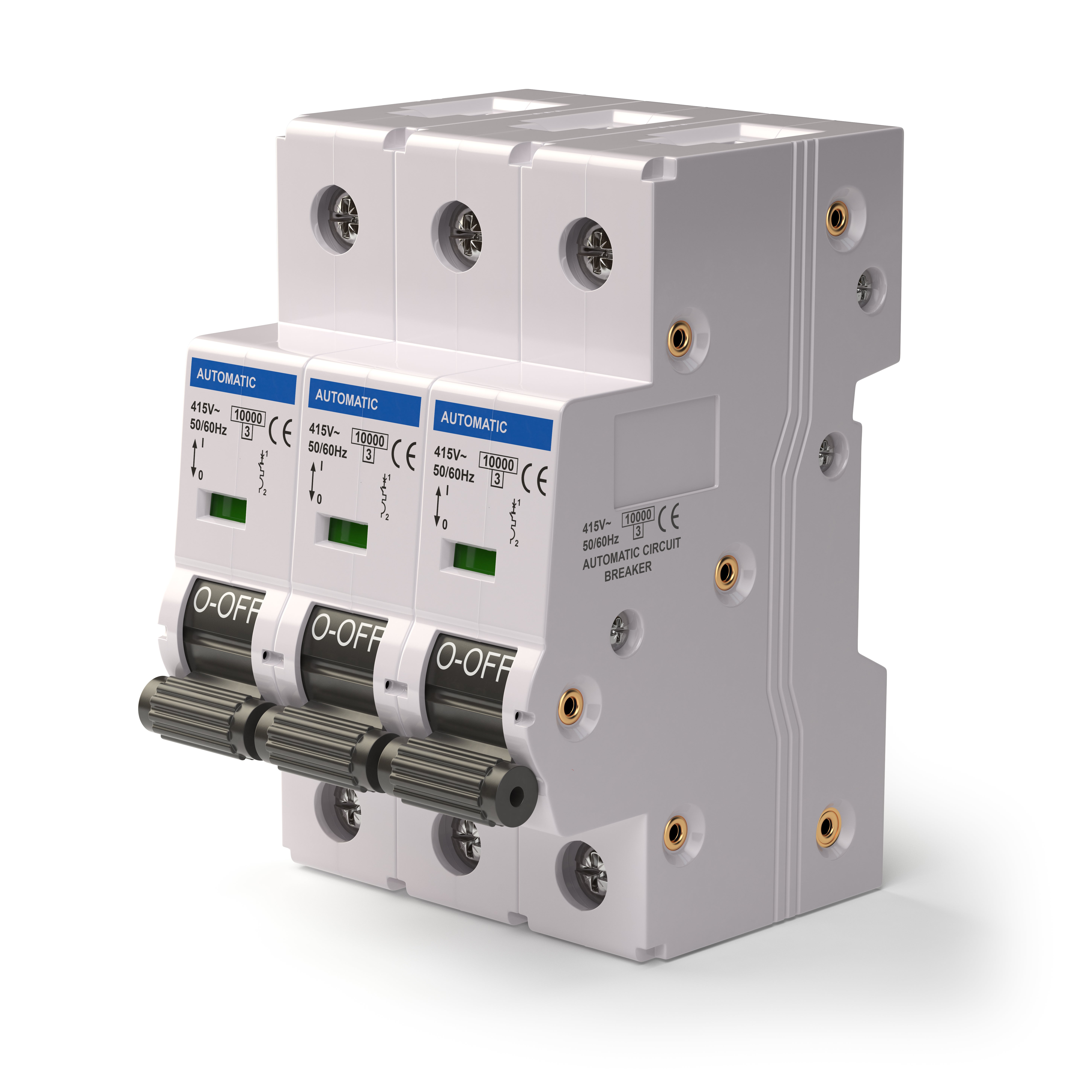
An electrical isolator is a form of mechanical switch that is used selectively to break off part of an electrical circuit where isolation is likely to be required. Imperative to the regulation and safety of the electrical system, this device is necessary for management during the system’s maintenance. Isolator switches are designed to be switched only under no-load conditions; in other words, it is only switched when no current is flowing through the circuit. They are not intended to open on their own and one must never use an isolator to place a live circuit off.
Types of Electrical Isolators
Electrical isolators are important devices in power systems. These isolators are classified into three primary categories based on the system’s requirements:
1. Double Break Type Isolators
Double Break Type Isolators have three post-insulators. You will find a tubular contact or a flat male terminal within the central insulator and this terminal is set horizontally through the rotation of the middle post insulator. This rotation is made possible by a lever mechanism provided at the base of the given structure. This design guarantees a sharp separation of the circuits.
2. Single Break Type Isolators
Single Break Type Isolators consist of an arm contact divided into two parts: one part with the male contact and the other part with the female contact. These contacts move because of the relative movement of the post-insulator to which they are connected. Yet, on the opposite rotation of the post insulators, the arm contacts make contact, and thus, the isolator is closed.
3. Pantograph Type Isolators
Pantograph Type Isolators are preferred for their small size, occupying little space as compared to others. They form existing switchgear equipment; these are the post insulator and the operating insulator. The mobility of their structure enables them to work well especially in complex systems; this makes them suitable for current power systems.
4. Bus Side Isolator
Bus Bus-side isolators are directly linked to the main bus. They have the essential duty of actuating individual portions of the bus to prevent the entire system from degrading and to support the power system’s dependability and stability.
5. Line Side Isolator
Line Side Isolators are available for connection in the circuit by use of a feeder line. They help in isolating individual lines, thus allowing safe maintenance and operational flexibility while at the same time not affecting the entire system.
6. Transfer Bus Side Isolator
Transfer Bus Side Isolators are connected to the circuit with the help of a transfer bus, mostly in relation to transformers. They afford an opportunity for isolation of the transfer bus for services such as maintenance
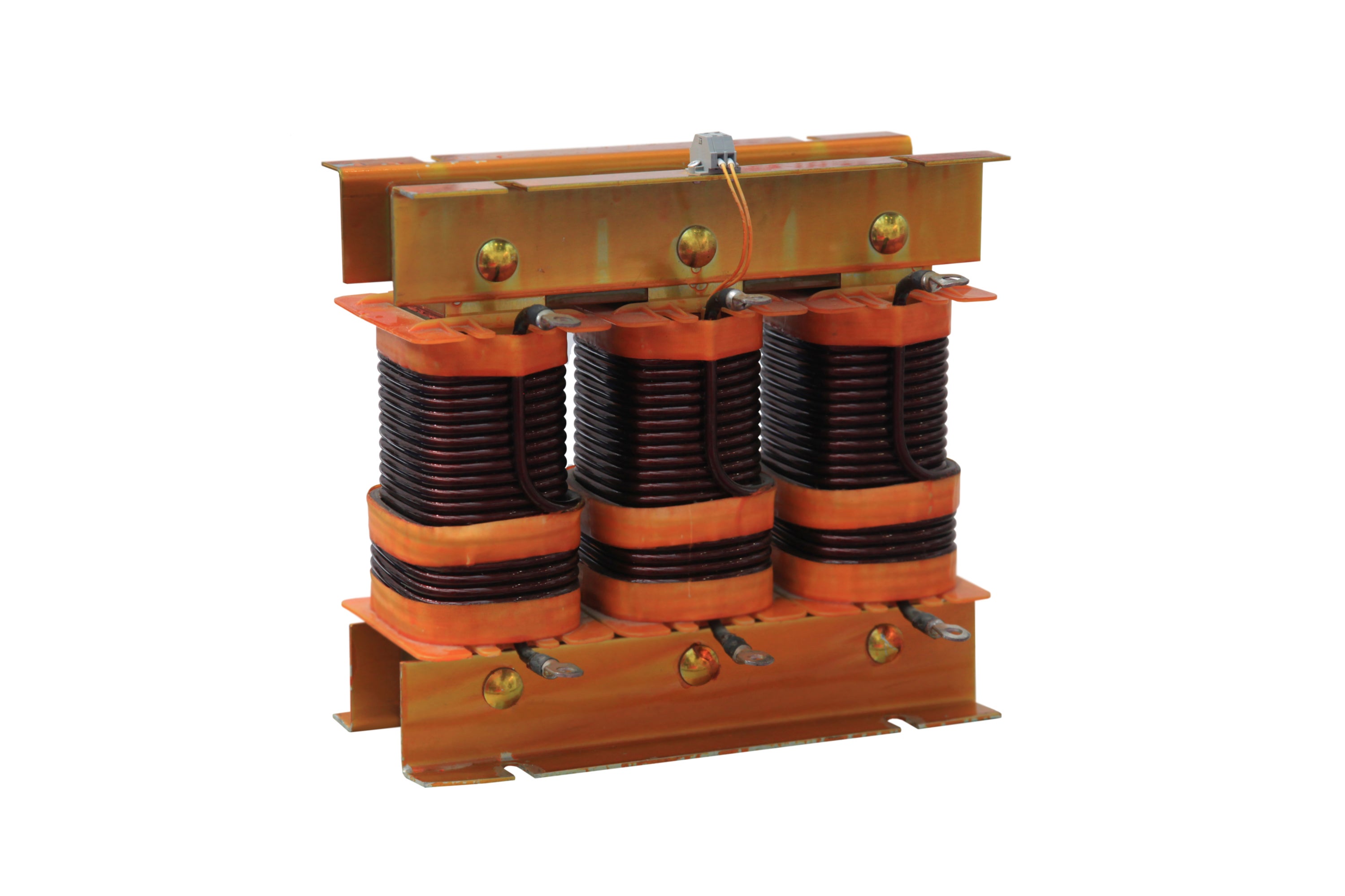
Electrical Isolator Working Principle
The working of isolator is very simple, and it can be used in both ways. These devices are frequently utilized as switches; such switches are called electrical isolator switches. Since there is a requirement to close or open the circuit by the switch, it has to be built in that way. However, they are often positioned to be stationary with the purpose of ensuring the working and troubleshooting are improved.
An electrical isolator switch is defined as a specific device that is intended to disrupt the circulation of current to a certain circuit for conducting secure maintenance and operation of electrical circuits. They are keyed in numerous electrical devices, such as kitchen appliances and electricity distribution networks. They are of various ratings according to their usage as single pole, double pole, three poles, four poles, fused, and battery isolator switch.
1. Open Circuit Condition
When the isolator is switched off, the contacts move apart and create an open circuit. This stops current flow completely. The visible gap ensures safety. It clearly defines the function of the isolator during maintenance and inspection work.
2. No Arc Operation
Isolators are used only when there is no current. This prevents arc formation between contacts. It increases device life. This working condition adds to the advantages of the isolator and keeps the operation safe and controlled.
3. Manual or Motor Control
Isolators can be operated manually or through motors. The mechanism moves contacts apart or together. This simple action ensures circuit control. Selection depends on system size and the electrical isolator sizes used in installations.
4. Safety Confirmation
The open position of an isolator gives visual confirmation. Workers can verify that the circuit is disconnected. This reduces risk. Proper labeling with the electrical isolator symbol also helps in quick identification and safe handling of equipment.
Uses of Electrical Isolators
Electrical isolators are mainly used to ensure safety during electrical maintenance. They disconnect circuits fully, so no current flows. The use of isolators is common in power systems where physical separation is needed before repair or inspection work begins.
1. Maintenance Isolation
During repair work, isolators disconnect equipment from the power source. This prevents accidental shock or damage. Workers can safely inspect or replace parts. The function of the isolator in this case is to create a visible break in the circuit before any manual work starts.
2. Emergency Shutdown
Isolators are used to quickly cut off power in emergency conditions. It helps reduce the risk of fire or equipment damage. These devices are simple and reliable. Their role in emergency systems adds to the advantages of the isolator by offering quick response without complex controls.
3. Equipment Protection
Sensitive machines require isolation during faults. Isolators help disconnect faulty sections without affecting other parts. This reduces downtime and repair costs. The uses of isolators extend to protecting motors, transformers, and other heavy electrical equipment in industrial and commercial settings.
4. Circuit Separation
In complex wiring systems, isolators help divide circuits into sections. This allows better control and easier fault detection. Technicians can work on one section while others remain active. The use of proper markings, like the electrical isolator symbol, helps identify switches clearly in circuit diagrams.
Application of Electrical Isolator
Electrical isolators are used to disconnect circuits for maintenance and safety. They are placed in different power systems where clear separation is needed. The applications of isolators include industrial panels, substations, and control units, where safe handling of electrical flow matters during inspection work.
1. Industrial Power Distribution
In industrial setups, isolators are fitted in main and sub panels to cut off power during servicing. They help protect workers from accidental current flow. The design depends on load demand and space. Proper selection also considers electrical isolator sizes to match system capacity and layout.
2. Substation Switching Systems
Substations use isolators to separate faulty sections from live systems. These devices work without a load and ensure safe inspection zones. Operators rely on clear open positions to confirm isolation. The function of the isolator here is simple, yet vital for keeping equipment safe during scheduled maintenance tasks.
3. Renewable Energy Installations
Solar and wind systems use isolators to disconnect generation units from grids. It helps during repair or an emergency shutdown. These units must handle outdoor conditions and varying loads. The applications of isolators in such setups ensure stable operation and prevent damage during sudden faults or overload conditions.
4. Commercial Building Panels
In large buildings, isolators are used in distribution boards to isolate sections like lighting or HVAC systems. It allows easy servicing without shutting down the whole system. Designers choose proper ratings and electrical isolator sizes to match wiring layouts and ensure smooth and safe operations.
Benefits of Using Electrical Isolators
Electrical isolators provide safety and control in power systems. They ensure circuits are completely disconnected before work begins. The advantages of isolators include easy operation, clear visibility, and low maintenance needs, making them a common choice in many installations.
1. Improved Safety
Isolators reduce the risk of electric shock by fully disconnecting power. Workers can confirm the open position before starting work. This builds trust in system safety. Clear labeling using the electrical isolator symbol also helps users quickly identify isolation points in panels.
2. Simple Design
These devices have a basic mechanical structure, which makes them easy to use. There are no complex parts involved. This simplicity reduces failure chances. It also supports the advantages of the isolator by making maintenance and operation straightforward for technicians.
3. Cost-Effective Solution
Isolators are affordable compared to other switching devices. They require less maintenance and last longer. This makes them suitable for many applications. Choosing correct ratings and electrical isolator sizes ensures long service life and proper system performance without extra cost.
4. Clear Visual Indication
One key benefit is the visible open or closed position. Operators can easily confirm isolation. This reduces errors during maintenance. The clear break also supports safe working conditions, which adds to the overall reliability and use of isolators in different systems.
How Do Electrical Isolators Work
Electrical isolators work by physically separating contacts in a circuit. They operate only when no load is present. This ensures safe disconnection. The design allows clear visibility of open contacts, which is important in many applications of isolators across power systems.
1. Mechanical Operation
Isolators use a manual or motor-driven mechanism to open and close contacts. When opened, the contacts move apart and break the circuit. This creates a safe gap. The working principle supports the basic function of the isolator in ensuring no current flows during maintenance.
2. No Load Switching
Isolators are not designed to interrupt current. They operate only after the circuit is de-energized. This prevents damage to contacts. Their use in no-load conditions makes them reliable and safe, adding to the known advantages of isolators in controlled environments.
3. Contact Separation
The contacts inside an isolator are designed to move apart with enough distance. This prevents accidental arcing. The spacing depends on the voltage rating. Engineers select proper designs based on system needs and electrical isolator sizes for effective operation.
4. Visible Isolation Gap
One important feature is the visible gap between contacts. It gives assurance that the circuit is open. This is useful during inspection and servicing. The presence of clear markings, including an electrical isolator symbol, helps identify the status quickly.
Common Faults in Electrical Isolators and How to Fix Them
Electrical isolators may face issues due to wear, poor maintenance, or environmental factors. Regular checks can prevent failures. Understanding faults helps maintain safe systems. These issues can affect the use of isolators if not addressed on time.
1. Contact Wear
Frequent operation can wear out contacts. This leads to poor connection or overheating. Cleaning or replacing contacts solves the issue. Regular inspection is important to maintain the proper function of the isolator and avoid unexpected failures during operation.
2. Corrosion and Rust
Outdoor isolators may develop rust due to moisture. This affects movement and performance. Applying protective coatings and routine cleaning helps fix this problem. Proper care ensures reliable applications of isolators in harsh environmental conditions.
3. Loose Connections
Loose terminals can cause heating and voltage drops. Tightening connections during maintenance prevents this fault. It also improves system efficiency. Proper installation and checks support the long-term advantages of the isolator in electrical systems.
4. Mechanical Failure
Moving parts may get stuck due to dust or a lack of lubrication. This affects smooth operation. Cleaning and lubrication restore proper movement. Regular servicing ensures isolators work correctly and support safe use of isolators in daily operations.
Also Read: What Is The Difference Between A Circuit Breaker And Isolator?
Conclusion
All of the isolators have specific functions and applications providing different means for disruption of electrical circuits in residential as well as industrial usage. It, therefore, can be said that an electrical isolator switch is very useful and is a necessity when it comes to electrical safety and reliability, hence making them key players in the current electrical network. So, choose the best ones from reliable providers. It is where Lauritz Knudsen Electrical & Automation can help you shop for the best isolators online.
FAQs
Q. What is the purpose of an electrical isolator in a substation?
Ans. The primary function of isolator units involves disconnecting a specific part of the grid for maintenance. It creates a visible physical gap in the circuit. This ensures safety for technicians working on high-voltage gear. It does not stop current flow but maintains a safe open state after the power is cut.
Q. How does an electrical isolator differ from a circuit breaker?
Ans. A circuit breaker handles heavy electrical loads and trips during faults. An isolator only operates when no current flows through the lines. While the breaker acts as a protector, the use of isolators focuses on total separation. You must open the breaker before moving the isolator handle to avoid dangerous arcs.
Q. What is the voltage rating of a typical electrical isolator?
Ans. Ratings depend entirely on the specific substation design and local grid requirements. These devices handle everything from 11kV in local distribution up to 765kV for massive transmission lines. Engineers choose a rating that matches the maximum system voltage. High-voltage models require large porcelain or composite columns to prevent flashovers during operation.
Q. What is the typical lifespan of an isolator switch?
Ans. A robust switch usually lasts between twenty and thirty years with proper care. Metal parts need regular grease to prevent rust or sticking in outdoor weather. Since it has few moving parts compared to a breaker, it stays reliable for decades. Regular testing of the contacts ensures the device works when needed.
Q. How is an isolator different from an MCB?
Ans. An MCB is an automatic device that snaps shut when it senses a short circuit. It protects your wires from burning. In contrast, the function of isolator hardware is purely manual and lacks any internal protection logic. You use it to switch off power manually so you can safely touch the wiring.
Q. Is an isolator the same as a circuit breaker?
Ans. No, these two tools perform different jobs in a power system. A breaker is a complex machine that can extinguish hot electrical arcs. An isolator is a simpler mechanical switch. One of the main uses of isolators is to provide a secondary safety layer that a digital breaker cannot offer.
Q. Why is an isolator installed on both sides of a circuit breaker?
Ans. Maintenance crews put switches on both sides to completely trap the breaker in a dead zone. This prevents backfeed from other transformers or live lines. By opening both ends, the breaker becomes totally isolated from any energy source. It allows for safe repairs or replacement without any risk of accidental shocks.